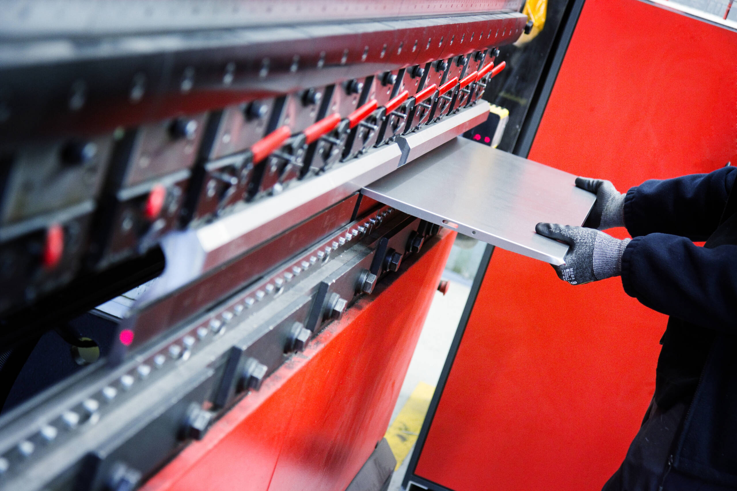
We offer bending services for a lot of sheet metal parts. The materials we can bend varies based on the material and thickness. Be sure to check out our resource page to see our full list of materials, design parameters, and limitations.
What is a CNC press brake?
A CNC press brake is a machine specially designed for bending sheet metal & plate materials. It uses a combination of a punch and die to achieve these bends. CNC control (computer numerical control) allows precision and accuracy. But, bends can only be accurate if they’re designed properly! See below for some guidelines on bending.
How should I design my part?
We use Amadas BendCAM software to manage your 3D file to produce our cnc program. If you are unsure about the IR you should apply to your part, rule of thumb is model half the thickness of the material i.e 6mm material 3mm Inner Radius. Our Software can manage the model and apply the suitable tooling to ensure an accurate finished parts.
Designing your parts in a CAD program will typically yield the best results. Programs like Fusion360, Solidworks, & OnShape have robust sheet metal design which allows you to design a part with the program handling the calculations for bend deduction, etc. If you don’t have access to CAD software you can design your part in the flat and calculate the bend deductions needed based on the charts below. This is a down and dirty method, but it can yield fairly accurate results if you take your time.
We can also help with files if needed! Reach out to use via email @ [email protected]
Materials
Here’s a list of common materials and their appropriate bending parameters
Here’s how to use this chart to design your parts…
The two biggest factors in your sheet metal design are K-factor & radius. If you’re using a 3D CAD software you can set up a new rule or set your parameters around this to get very accurate parts made! We physically cut and tested all of these settings to ensure they’re as accurate as possible! But, if you won’t have access to a 3D CAD software you can use the “Bend Deduction” amount to manually draw your parts in the flat pattern. This number is the amount the material will stretch, so you would deduct (or take away) that amount from your flat pattern on each bend. The bend deduction method should still get you very close when designing your parts!
Other things to note in this chart.
⦁ Minimum flange length: This is the smallest allowable flange based on the material you select. There can be some exceptions, but this is standard for 99% of bends.
⦁ Distortion Zone: This is the area right next to the bend centerline that you won’t want any holes or features. If you need to have features in the “distortion zone” you could add a relief slot along the bend centerline of switch to a different thickness material.
⦁ Max Length Of Part: This is the longest part we can bend with the selected material. As we upgrade our machines and tooling we can hopefully increase these numbers. But for now this is our limit for length.
Other things to note in this chart.
⦁ Bend relief or slit This will eliminate the distortion zone allowing holes and features to be really close to your bend centerline. Keep the slit the same width as the feature you’re trying to keep from distorting. Example: if you have a 0.25” diameter hole make the slit 0.25” wide, parallel with the hole.


